
You will want to include various things when creating a CNC technical drawing. For example, you can include the Isometric, Section, Dimensioned, and Notes to the manufacturer. This will help the machinist knows what to do and what not to do. These elements ensure that the CNC machined part is made to spec.

Isometric views
Isometric views in a CNC Technical Drawing show the object in three-dimensional form. The first view is a front view. The next two views are sided views. A third view shows the object from an angle of thirty degrees. These views are useful for describing the perspective and depth measurements of a 3D object.
The isometric view gives the machinist a better understanding of the part’s geometry. It may also offer valuable information on build orientation or installation direction. On the other hand, the section view describes the internal features of a part and is usually positioned in line with the orthographic view.
When dimensioning features, you should include the measurements for each one. For instance, if you’re defining the thread depth, specify it in the ballot as a minimum. Another rule is that multiples of the same feature should be given only one dimension. You can add “#X DIM” to a feature.
A CNC technical drawing must include at least two isometric views. The coordinates are placed on the sides and borders of the drawing to serve as reference points for discussing the contents of the drawing. In most cases, the orthographic view will give the most accurate information about geometry, including dimensions and tolerances. Because it is a 2D representation of a 3D object, it may include hidden lines. The goal of the drawing is to provide enough information to the user.
Isometric views are useful for visualizing the 3D form of a part. They can be created using the orientation icon in the part file or the view orientation area in the view properties dialogue box. The axes can be rotated by 45 degrees around the vertical axis and 35 degrees around the horizontal axis. The line display can be controlled independently for each view, but a semi-sectional view generally does not display the fine detail of a part.
The detailed view can help highlight areas of the orthographic view that may be difficult to see and dimension. A detailed view is generally placed at the bottom-left corner of a technical drawing. It also features a letter that signifies the area.

Section views
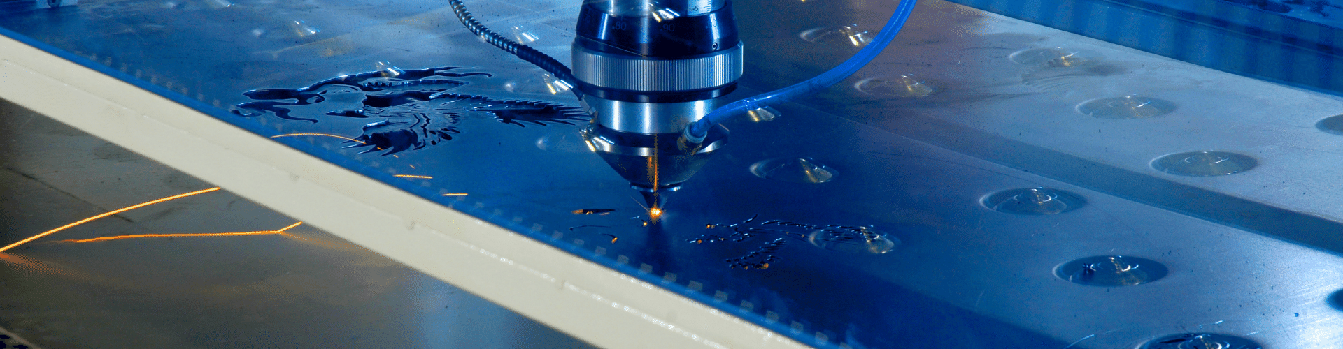
Technical drawings are used to present the internal details of a machined part. They are also useful for explaining features that may not be visible in the main view. For example, section views may be required for internal features that are difficult to dimension. Section views are also often used to illustrate the centerline of circular patterns and holes. They should also include annotations and critical dimensions.
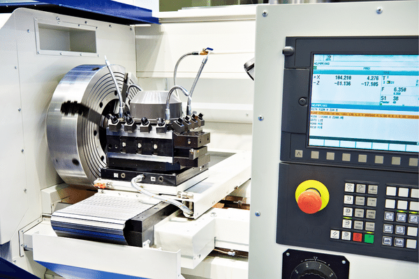
CNC technical drawings should have at least three orthographic views and a section view to show the internal features of a part. Section views can be easily added by selecting ‘Model View’ on the ‘View Layout’ tab. SOLIDWORKS provides instructions for adding drawing views. For most CNC machining drawings, two or three orthographic views are enough. Ensure they are scaled correctly to leave enough space for notes and dimensions.
Technical drawings can also include notes for the manufacturer. Adding notes to a CNC technical drawing can help communicate details. Although they are not required to receive a quote, they help to convey important details and requirements. For example, you can specify whether a component needs to be deferred or have specific surface finishes. It is also useful to reference another CAD file or component in the drawing.
Section views in a CNC technical drawing should be clear and concise. A broken-out section will reveal the inner details of a machined part. It is important to note that the profile of a broken-out section is defined by its closed profile, which is typically a spline. A reference position also indicates the depth of a broken-out section in another view.
Section views are the most important views to include in CNC technical drawings. They help to highlight the details of a part without overstretching it. For example, they help to show the size and position of the interior step of a machined part. Moreover, they can help to reduce the number of dimensions in the drawing.
Including multiple section views in a CNC technical drawing is crucial to manufacturing. This will ensure that you get the right details and avoid guesswork. These views should be well-proportioned and feature most of the part’s features. Often, these views are portrayed without dimensions.

Dimensioned geometry
Dimensions are important to ensure accuracy during the manufacturing process. They also define the nominal geometry and allowable variation of a part. They cannot be calculated directly from a drawing or model. However, casual CAD users may be accustomed to adding dimensions or measuring them directly. Dimensions should be clearly defined on the technical drawing. Every dimension and tolerance that are required to define the finished part should be specified. In addition, it is important to use a consistent baseline for all dimensions.
When creating CNC technical drawings, dimensional geometry is an important component to consider. Dimensioned prints provide accurate information about the part to help machine it. For instance, if a hole is a critical feature, it is important to dimension it appropriately. A hole is often machined using a drill, so its dimension should be standardized. The dimensions of secondary features should also be noted.
Orthographic views are a crucial component of a technical drawing. They convey most of the geometry information by representing the shape of the part in two dimensions. The orthographic view also contains hidden lines important for communicating features and dimensions. Typically, two or three orthographic views will be sufficient to communicate the geometry of a part.
Dimensioned geometry should be included in the orthographic and detail views. Ensure that the orthographic views are center-placed and allow ample room for the dimensions. For those areas that are difficult to dimension, use detail or section views. Additionally, include tolerance values for critical features.
Geometric Dimensioning and Tolerancing (GD&T) is a language of symbols and standards that manufacturers use to communicate with each other. It was developed in the 1940s by the US military and is now widely used throughout the industry. The language of GD&T facilitates communication and helps ensure quality in manufacturing processes.
A technical drawing must include construction lines, center marks, dimensions, threads, and tolerances. It should also contain a title block, annotations, and notes.

Notes to manufacturer
When creating a CNC technical drawing, it is vital to include notes to the manufacturer. This is typically located in the bottom left corner of the sheet, above the title block. These notes will explain the specific requirements for the part-wall lettering and other details specific to the manufacturer. In addition to providing specific instructions, the notes should include the necessary measurements and tolerance values.
To ensure that the part is produced exactly as intended, include details about surface finishes, deburring, and cleaning. You can also include information about material certifications and various requirements. This will improve the manufacturing process and ensure your satisfaction with the result. In addition, it will help the manufacturer to make the part that you want.
Technical drawings are a key part of manufacturing. Accurate engineering drawings help manufacturers create parts that are functional and aesthetically pleasing. However, they can be challenging to create. For example, engineers often struggle to decide which dimensions to include and which requirements to leave out. It’s also difficult to strike the right balance between providing too much information and not enough. Engineers may consider working with a trusted manufacturing partner to overcome this problem.
Technical drawings include many details vital to the successful production of CNC machining. These include dimensions and tolerances, as well as other relevant information. This is especially important for manufacturing components that require a lot of precision. In addition to technical drawings, engineering change notices and 3D model datasets should also be included.
Using technical drawings is an excellent way to communicate complex mechanical processes. They help manufacturers identify the areas that need to be checked and the features that require tight tolerances. They also offer several key views of a part, including cross-sections of features that are not visible to the naked eye. They also contain specific notes to the manufacturer.