


Here at ETCN, we provide machine shops with a huge selection of metals and machine parts designed for CNC machining. If you are new to CNC machining, or you’re simply looking for better ways to design your parts than you have in the past, I’ve got some useful information for you.
What is CNC Machining?
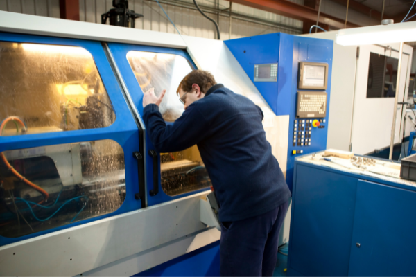
CNC machining is a process used to create parts from raw materials. It involves using computers to control a machine that cuts and shapes the material into the desired form.
The process is used for many applications, including making airplane parts, drilling holes, milling, and turning.
CNC machining is often confused with 3D printing and computer numerical control (CNC). But these are three different processes that can be used together or separately depending on the needs of your project.
CNC machining can be expensive compared to other manufacturing processes such as injection molding or stamping, but it provides high precision. The process produces consistent parts in size, shape, and surface quality, making them ideal for use in industrial applications where safety and performance are paramount.

Material Selection
Material selection is one of the most important decisions when designing a part for CNC machining. There are many considerations to take into account when selecting material, such as:
Cost: The price of a material can vary greatly depending on its composition and application. Using a more expensive material may make sense if you can achieve better results or more quickly.
Strength: Parts that require high strength should be made from materials with high tensile strength and yield strength. In these cases, carbon steel alloys are typically used due to their relatively low cost and ability to withstand high loads.
Ductility refers to a material’s ability to deform under stress without breaking or fracturing. Materials with good ductility typically have elongation values greater than 20% before breaking. In some cases, it may be preferable for a part not to deform during machining operations (such as when making precision holes). In these cases, a material with low flexibility (such as stainless steel) could be used.

Drafting a technical drawing
Drafting a technical drawing is the first step in CNC machining parts. To draft a technical drawing, you must first determine what type of part you want to produce. There are many different types of parts that can be produced with a CNC machine, including:
Round Parts: Round parts are typically used in manufacturing because they are easy to manufacture and have no flat surfaces. They are also extremely versatile and can be made in any size or shape.
Square Parts: Square parts have four flat sides and one curved side. This makes them easy to produce on a CNC machining center because all edges are straight lines that can be cut with a router bit. The only problem with square parts is that they often have rounded corners which can be difficult to produce on a CNC machine because round bits cannot cut corners effectively.
Rectangular Parts: Rectangular parts have four flat sides and two curved sides. Rectangular parts are very common because they can easily be produced using two cutting tools, one for each side (top & bottom). This makes them an excellent choice for producing custom boxes or similar items requiring two cuts per side (top/bottom).
Specialty Parts: Specialty parts include any type.

CNC machine setups and parts orientation
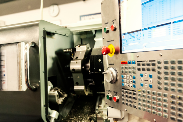
CNC machines cut or grind materials, such as metal and plastic. The machines have a set of axes that move the cutting tool in multiple directions. CNC programs are created to tell the machine how to move to make cuts or shapes in the material.
When designing parts for CNC machining, there are several things you need to consider:
CNC machine setup: A CNC machine has three axes: X, Y, and Z. These axes determine which direction the tool moves in — X moves left and right, Y moves up and down, and Z moves forward and backward. Each axis has its motor, which controls its movement.
Parts orientation: The orientation of your part can affect how much material you remove when machining it. Parts should be designed with this in mind so that they don’t need excessive amounts of material removed from them to become functional components.
Part size: Part size and orientation is the most critical setup in a CNC machining process. The correct part size and orientation ensure that the part fits in the machine, the tool path is generated correctly, and even more importantly, it allows for efficient material removal. If any of these steps are incorrect, there can be severe consequences on your part quality and overall production time.

The process of CNC machining
The CNC machining process is straightforward: a computer-controlled machine follows its instructions, cutting a precisely defined path through a block of material.
But what happens when you want to design parts for CNC machining? The process isn’t quite as straightforward.
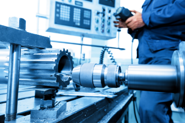
CNC machining is a subtractive manufacturing process. That means you start with a larger piece of material, cut it down to size and then remove excess material from the piece until your design is complete. The cutting tool can be an electric drill, milling bit, or router bit — whatever it takes to remove the necessary material from the part.
There are several different types of CNC machines that perform these operations. They’re all programmed using CAD files and software like SolidWorks or AutoDesk Inventor HSM (High-Speed Machining).
The first step in any project is to determine how much material needs to be removed from each surface so that your part meets its functional requirements while being affordable enough to manufacture. If this sounds like rocket science, don’t worry — plenty of free online tools can help get you started on the right track.

CNC design guidelines
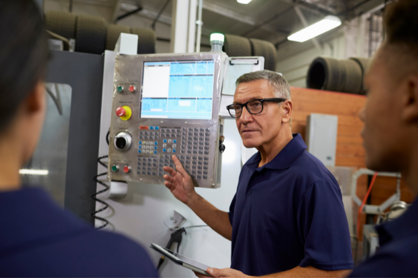
When designing parts for CNC machining, there are several things you can do to make the process easier and more efficient. Following these guidelines ensures that your parts are ready for machining on a CNC machine.
1. Make sure your part is water-tight and does not leak when it’s filled with water.
2. Ensure that all holes are drilled perpendicular to the surface.
3. Make sure all threaded holes are properly before being milled out. This means that they need to be drilled perpendicular to the direction of the threading so that they don’t come out at an angle when they’re cut by the milling tool or drill bit (which would result in poor quality threads).
4. Ensure that all holes have adequate size for tapping so that tapping can be done without stripping or breaking off any threads in the hole itself (which would require re-tapping).

Design Limits for CNC Machining
Design Limits for CNC Machining
There are several important factors that you need to consider when designing parts for CNC machining.
The first is the size of your machine. The spindle diameter, length, and speed determine how large a part you can make on a particular machine. In addition, if your machine has a vertical spindle, it can handle larger parts than a horizontal spindle.
The second consideration is the material that you are using. Different materials require different cuts to maintain dimensional accuracy while machining them. Also, some materials are not suitable for CNC machining at all. For example, plastic and wood cannot be machined with most machines because they cannot withstand the heat produced during cutting operations. Some plastics can be cut with special tools designed for cutting plastic. Still, these tend to be very expensive and are therefore not practical for most hobbyists or small businesses who do not have access to expensive equipment like this.
The third consideration is the tolerance of your parts and how much variation you expect from the finished product after it has been cut by the CNC machine operator, who will use their software program to control your machine operation. In contrast, it cuts your parts out.

Conclusion
You can learn the most from this table by actually designing a part. Start with an idea, make it on paper, then take it to the software and machine. Sooner or later, you will find that some of your designs cannot be made, and you’ll have to redesign them to make them workable. Going over this table will help you understand why certain features are not suitable for CNC machining and give you ideas on how to design parts that are more suitable for CNC machining. I hope this article helps people get a good grasp of the basics of designing parts that will be machined on a CNC milling machine.