


This post will cover some of the best ways to improve the design and decrease cost while optimizing machining with CNC milling processes. Then it is time to go through fillets, chamfers, configuration, drilling, tapping, undercutting, and texting. CNC machines. CNC-milling machines are used in converting raw materials into final parts using cutting away material.

How to design parts for CNC machining?
CNC machining is an abbreviation for Computer Numerical Control. It is a type of manufacturing process used to create parts. This process uses computers and machines to control the cutting tools that are used to cut the material. CNC machining can be done on many different materials, including plastics, metals, and other materials.
The first step in designing a part for CNC machining is to understand the requirements and specifications of your project. You will also need to determine if you want to use one or more operations for each part you are creating.
Once you have gathered all of your information, it’s time to begin creating your design in CAD software like SolidWorks or Autodesk Inventor. Once you have created the design, it’s time to send it off for inspection by an expert who can give you feedback on any issues that may arise during production or assembly.
Once your design has been approved by your expert, it’s time to send it off for production with your chosen CNC machine shop!

Machine types
The most common type of CNC machine is an XYZ milling machine (also known as a vertical milling or lathe). This type of machine has three axes: X (for horizontal movement), Y (for vertical movement), and Z (for depth of cut).
When designing for milling machines, you need to take into account how each axis will affect your model’s design. For example, a part with only one surface won’t have any issues with creating holes on a single axis — but if you need multiple holes on that same surface, then you’ll need to think about how they will line up with one another.
In addition to knowing how each axis works, it’s important to also understand how different types of cutters work on each axis. For example, some cutter bits are designed specifically for use on flat surfaces while others are better suited
Basic rules
There are some basic rules that you need to follow when designing a CNC machine.
The first rule is that every part of your CNC needs to be made out of metal. This includes the frame and any other parts that are attached to it. The only exception is if you’re using an aluminum box or sheet for the frame, in which case there should be no plastic parts anywhere.
The second rule is that the entire CNC needs to be built from scratch using only basic tools like drills and saws. You can use jigsaws to cut out holes for bolts, but there should be no electronic tools used during construction other than perhaps a power supply for a drill or saw (if necessary).
The third rule is that all parts must be designed using CAD software such as SolidWorks or FreeCAD. You have to design everything from scratch so it will work properly with your machine’s capabilities.
CNC machining undercuts
CNC machining undercuts is a process that involves using a CNC machine to produce undercut parts. The toolpaths used in this process are often referred to as “undercutters”. Undercutters are based on the concept of generating toolpaths that allow for cutting the underside of the part with a smaller diameter tool than the top surface. This can be done by either changing the depth of cut or offsetting the toolpath from the centerline of the part.
In order for an undercut to be successful, there must be at least one feature within the part that is solid enough to support itself with no help from other features or from support structures. If not, then traditional machining methods will likely have to be used instead of CNC machining undercuts.

CNC machine setups and parts orientation
CNC machines are used to cut, drill, or mill various materials such as wood, plastic, metal, and even food. If you want to learn how to use a CNC machine, then you’ll need to know how to set up the machine tools and how to orient the parts correctly so that they will be cut correctly.
Setting up your CNC machine:
The first thing that you need to do when setting up your CNC machine is to make sure that everything is level. You can do this by measuring from corner to corner on each side of the table. Make sure that all measurements are the same number of inches away from each other. Once you have determined that everything is level, then you can move on to installing your software onto your computer and setting up the controller for communication with your computer.

Parts Orientation:
Orienting parts correctly on a CNC machine can be tricky but if done correctly will ensure that parts are cut properly without any issues later down the road. When orienting parts on a CNC machine, there are three main things that need to be considered:
First the type of material being machined. This will determine the type of clamping fixture you need to use. Wood and plastic will generally require some clamping mechanism, but steel parts can be held in place by using a vice or chuck.
Second, the size and shape of your part. These two factors are closely related because if you have a small part then it will be easier to hold in place than if the piece were larger. Similarly, if you have a complex shape then you may need more than one way to hold it so that it doesn’t move while cutting.
Third, your budget for this project and any future ones like it. If you have enough money then there are many different types of jigs and fixtures that can help you hold your pieces securely in place during machining operations. However, if your budget is limited then there are still ways to make sure that your parts stay where they should even though they won’t provide as much support as other methods might offer
Design for CNC machine parts
Design for CNC machine parts is a very important in the overall design process. As a manufacturer, you need to be aware that your part will be produced in a very different way than conventional processes. The material is removed from your part using a milling cutter and not by an abrasive like sandpaper. This means that you need to follow certain rules when designing your part so that it can be milled on a CNC machine without problems. If you don’t follow these rules, you risk having your parts fail during production or even worse, have them fail during use by your customers.
1. Avoid sharp corners and edges
2. Reduce overhangs as much as possible
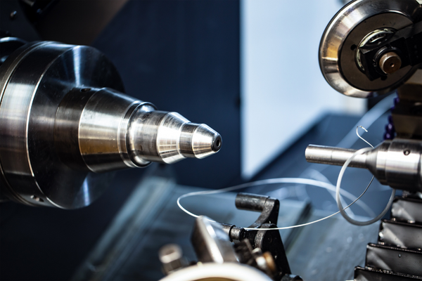
Tell me the CNC machining process?
Machining is one of the most widely-used processes in industry. Machining is the process of cutting, shaping and forming metal or plastic using a variety of tools. Machining can be done manually with hand tools, but it is usually done with machine tools such as lathes and milling machines.
The machining process involves five stages:
1. Tool design
2. Cutting tool preparation
3. Part preparation
4. Cutting operation
5. Finishing operation
CNC design guidelines
This is a list of guidelines you should follow when designing your parts in CNC machining. The goal of this list is to help you make parts that are easy to machine, have a low chance of error and are easy to assemble.
1) Use simple shapes
2) Keep holes on the top surface
3) Keep pins on the bottom surface
4) Keep notches away from edges and corners
5) Avoid undercuts where possible
6) Use round holes for smooth cutting and easier tapping if needed

What is 5-axis CNC machining?
5-axis CNC machining is the process of using a computer numerical control (CNC) machine to make complex parts. The process involves the use of five axes of motion, adding a new level of precision and control to CNC machining, which is traditionally performed on three axes.
Five-axis CNC machining machines are used in industries such as aerospace, automotive and medical device manufacturing. The increased flexibility provided by these machines allows even more complex parts to be created than was previously possible using only three-axis machines.
The additional axis allows for greater precision in both 2D and 3D machining operations. While there are many different types of five-axis machines available, they all have essentially the same design and function: they move along four axes while rotating around one axis at a time.
The additional axis gives manufacturers more control over their workpieces during each step of the manufacturing process, allowing them to create more intricate parts with fewer errors or defects than would be possible if only three-axis machines were used.

Drafting a technical drawing
Drafting a technical drawing is the process of creating a drawing that shows how something should be manufactured or assembled. The drawing might show how to make an individual part or it could show how to construct an entire machine. Drafting is done by professional engineers, drafters and designers who use special computer-assisted design software called CAD.
CAD programs allow the user to draw objects on a computer screen by using lines, curves and shapes. The object can then be manipulated in many ways using commands from the keyboard. The resulting image can be printed out as a hard copy or exported to other software programs for further manipulation.
Drafting is used extensively in manufacturing industries where it helps reduce the costs associated with designing new products and processes by allowing multiple people to work on different parts of the same project at once. This can also help make sure that each person involved in creating a product understands its overall structure so that they can collaborate more easily when developing new designs for future products.
What are the main limitations of CNC design?
The main limitations of CNC designing are:
1. It cannot be used to create two-dimensional shapes that are not flat or curved.
2. CNC designing does not have the ability to handle complex curves and non-linear surfaces as well as some other computer aided design (CAD) programs do.
3. CNC designing is not as good at producing artistic designs as other CAD programs are because it does not have sophisticated graphics capabilities such as those found in Adobe Illustrator or Corel Draw.

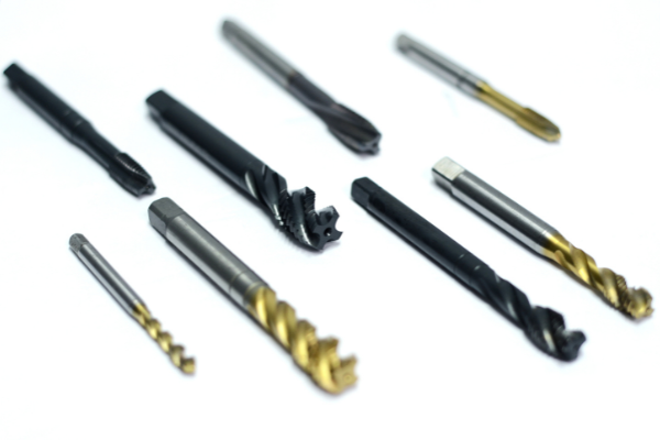
Threads, tapping & thread milling
Threads and Tapping
Threads are the external part of a hole, and in many cases they can be seen on the outside of an object. Tapping is a special tool that is used to cut threads in holes. The most common use for tapped holes is to mount threaded fasteners such as screws or bolts into the hole. The first step to cutting threads is to drill a hole that has the correct diameter for the desired thread size. This can be done by hand with a drill press or drill press attachment, or with a dedicated tapping machine. The next step is to tap the hole by using either a tap wrench or tap handle. This must be done carefully so as not to break off any chips that have been ground out by the tap itself while turning it into the drilled hole. The final step involves installing a screw into your newly tapped hole, which will create its own threads once it is screwed onto another object such as another screw or bolt head.
Thread Milling

Thread milling is similar in many ways to tapping except for several key differences. The first, and perhaps most important, is that a thread mill is designed to cut threads up to four times larger than a tap. This means that threads on large components can be cut with a single pass instead of multiple passes required by the tap.
The second difference between thread milling and tapping is that the tooling for thread milling uses a solid carbide insert rather than an HSS or cobalt cutting tip. This allows for much higher feed rates with less risk of chatter or breakage than tapping.
The third difference is that thread mills use an indexable insert instead of a standard tool holder like those used for tapping or boring. This means that the insert can be changed quickly and easily without having to remove the part from the machine and change the setup in your CAM program every time you want to use a different size or type of insert.
Undercuts
Undercuts are the most difficult part of a part. It is the area where the tool touches the material for a short period of time. The length of this contact is less than that of the rest of the tool path. The length of this contact can be calculated using a formula called as Undercut factor.
Undercut factor = (RPM / Feed per tooth) x Tool diameter
The RPM, feed per tooth and tool diameter are all directly related to each other, so you can use one value to get others. For example, if you know that your machine has a spindle speed of 3000 RPM and your feed per tooth is 0.05 mm/rev then all you need to do is divide these two values to get an undercut factor of 15 (3000 / 0.05 = 60). This means that your tool will make contact with the material for 15 seconds out of every minute as it moves around on its path.
Tool restrictions
The tool restrictions are important for the design of the CNC machine. If you want to make a drawing, then the drawing will be easily made by using the drawing tools. But if you want to cut a material, then the tool restrictions will be more careful. The other tools will also use some tools and materials, which may not meet the requirements of CNC machining.
If you want to make a drawing by using Cadsoft Eagle, then you must know how to use it correctly. You need to know what kind of drawings you can make and what kind of drawings are not allowed for making in Cadsoft Eagle.
The following are some restrictions:
1) You cannot use lines less than 1 mm thick or longer than 50 mm;
2) You cannot draw arcs with an angle greater than 360°;
3) You cannot have too many intersections;
4) Circle and ellipse should be closed or semi-closed;
Tool access

The most common metric for tool access is the distance from the center of a hole to the center of the next hole. In general, this distance should be less than twice the diameter of your largest tool.
Short tool access distances are critical for CNC machining. This is especially true when using multiple-spindle setups in which two or more tools must be located in close proximity to one another. If you don’t have enough room for these tools, it might be necessary to split your part into multiple operations or use a larger spindle (which could result in other issues).
Chamfers & Fillets
Chamfers and fillets are used to round off sharp corners, transitions or edges of a part. This helps create a more consistent look and feel to the part. The benefit of chamfers and fillets is that they improve the overall aesthetics of the part while reducing tooling costs.
The two most common types of chamfers and fillets are:
Chamfer – Chamfer is a bevel on one or both sides of an edge. It can be used as a transition between two surfaces, as in a corner or edge. A chamfer can also be used to reduce stress concentration in an edge, particularly at the root of an angle cut.
Fillet – Fillet is a rounded surface formed at an angle less than 90 degrees with another surface by means of machining or casting processes. It is often used to remove sharp edges from parts such as castings
Internal edges
Internal edges can be used on parts where the outer perimeter of the part is not important, but internal features must be machined. Examples include holes, slots, tabs, bosses and bosses with tabs. Internal edges can also be used to create features that cannot be made using external edges alone such as complex contours or fillets.
Inner edges
The inner edge of a machine tool is the moving part that moves toward the work. It is also called a cutting tool or simply an edge.
Undercut design for CNC machining

Undercutting is a design strategy that can be implemented with any tooling system. It involves creating a pocket or depression in the part surface to allow access to internal features during machining. Undercuts can be created manually by using a tool called an undercutter (or undercutter carbide lathe tool) or automatically through CNC machining.
Undercutting can be beneficial for many reasons:
Lowering costs: Undercutting allows you to use less expensive tools because they do not need to reach all the way into the pocket in order to remove material from the workpiece surface. This reduces tooling costs and makes it possible to use smaller tools that are easier to handle and maintain than larger tools would be if they had been designed specifically for this purpose.
What are advantages and limitations of 5-axis CNC machining?
1.The main advantage of 5 axis CNC machining is that it can produce complex shapes with good surface quality.
2.The main limitation of 5 axis CNC machining is that it requires a high level of skill and experience on the part of the operator, since there are more factors to consider during programming and machining.
3.In addition to the above points, there are other limitations such as:
-The cost of equipment, tooling and training is greater than in conventional CNC machines so this may be an issue for small businesses or hobbyists trying to get started with CNC machining.
-There are also additional costs involved with maintaining a 5 axis machine over time due to wear and tear on parts like ball screws or linear guides (bearings). These need to be replaced periodically as they wear out, so this can add up over time if you don’t replace them yourself or through professional services like a maintenance contract (if available).
What are CNC threading tools used for?
CNC threading tools are used to help you create complex shapes and designs. This can be done by using a CNC machining machine, which is a computer-controlled machine that can be programmed to perform tasks automatically.
The advantage of using this type of technology is that the process is much faster than it would be if you were to do it manually. You also have the benefit of working with materials that are too hard or too soft for manual threading, such as plastics or metals.
Can also be used to create holes in parts that need them. For example, if you want to drill a hole through an aluminum block to fit perfectly with another part made from steel, then you will need to use this type of tool for your project.
What is machining design?
What is machining design?
Machining design is the art of designing parts for a CNC (Computer Numerical Control) machine to make. It requires a good understanding of the manufacturing process, material properties and limitations.
Machining design is also known as CAM (Computer Aided Manufacturing). This is because it uses computers to generate the code that will be used by the CNC machine to cut out a piece of metal from another piece of metal. The design can be done manually or with software like SolidWorks or Inventor.
CNC machines are usually controlled by computer, which means they are programmable. This means that they can do things automatically without any human interaction necessary after the initial programming has been done. A program written in G-code (a language designed specifically for CNC machines) will tell a CNC machine where to move its various axes and what tools to use at each point in time during operation.
A CAD model can be imported into SolidWorks or Inventor and then converted into an STL file, which is an industry standard format used by most CAM programs such as Mastercam, Vectric Aspire 8 (formerly Cut2D), Corel Draw etc., so that the CAM software can interpret it correctly when generating
We hope that this collection of materials has proved to be of great help to you.