


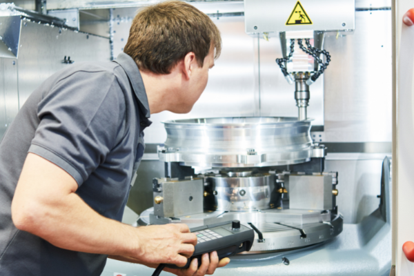
Machining is the most flexible of all the manufacturing processes. There are lots of designs that could be manufactured by machining. Product complexity, size, accuracy, and material properties usually influence the machining process selection. It would help if you went through some design guidelines while planning the machine as the cost and quality of this influence.
Choose the right materials
The materials used in machining are very important because they determine how well a part will perform under various conditions. For example, if you were making a pipe fitting from stainless steel, you would need to choose a material with good corrosion resistance so that it would not rust over time due to exposure to water or chemicals. If you were making a marine propeller shaft from cast iron, it would need to have high wear resistance to withstand the impact of waves on its surface without being damaged or worn away over time.

Avoid sharp corners
Sharp corners on plastic parts are more likely to break during machining than rounded ones. This is because a tool cuts into a corner and creates a stress concentration that can cause the material to crack or chip off. Sharp corners also make it more difficult for cutting tools to remove material from the part. Avoid sharp edges whenever possible; round them off with a file or sanding wheel before machining them.

Allow for machining space
Machining requires space between the workpiece and other objects. This space is called “clearance” and must be maintained during the machining process to avoid damaging your machine and the part being worked on. Clearances are generally expressed as minimum distances between two surfaces that might come into contact with one another during operation; they may also include other parameters such as thermal expansion (which can lead to warping) or vibrations caused by moving parts in your machine’s drivetrain).

Provide a good work or flat surface for clamping the part
The machining work surface is an important part of the setup process. It provides a good work or flat surface for clamping the part and supports the tooling during machining operations.
The work surface should be rigid and flat to ensure no deflection during tool engagement. A stable surface also helps reduce vibration and chatter, adversely affecting tool life and accuracy.
When choosing a work surface material, consider its compatibility with the machined material and the size of the parts you work with. For example, when machining aluminum alloys, you should use a steel surface plate to ensure that your cutting tools do not become coated with aluminum oxide particles that can damage them.
It’s also important to consider the space available for your machine tools and accessories on your shop floor or in your manufacturing area. If space is limited, consider mounting your machine tools on mobile bases so they can be easily moved around as needed.

Choose appropriate tolerances
The first step in machining is to choose the appropriate tolerances. It would help if you chose the largest tolerances possible that are acceptable for your parts. For example, if you need to make a hole 10 mm in diameter, you should use the largest possible hole size of 10 mm. This will allow you to produce the part as accurately as possible.
It would help if you also decided on the appropriate tolerances for each feature of your part. For example, if you want a shaft with a diameter of 10 mm and you have specified that it must be within 0.01 mm of this value, then it would be acceptable for the shaft diameter to vary from 9.999 mm to 10.001 mm.
It is important to note that some features may be more important than others and therefore require tighter tolerances. For example, if you need an accurate hole for your part to function properly, this feature would require tighter tolerances than other features such as slots or threads, which do not affect its functionality so much as its appearance and ease of assembly.

Use design features that are easy to machine
–Use round holes instead of square holes. The corners of a square hole can be difficult to cut out and cause tooling damage.
–Use tapers instead of chamfers. Tapers are easier to cut than chamfers because they have less material at the corner, which allows for more control over the depth of cut and tool life.
–Design with large radii in areas that require machining, such as inside 90-degree bends and corners with a radius greater than 1⁄8 in. These areas will help reduce chatter and tool wear during cutting operations.

Consider the material properties and level of difficulty in machining the material
When designing a part, there are several considerations that you should take into account. The first is the material properties, which will determine what process you can use to machine your part and what kind of tooling you need. Secondly, you need to consider the difficulty in machining the material.
Material properties
Material properties include density, hardness, and elastic modulus (stiffness). For example, if you have a very dense material with high hardness and elastic modulus, it will be difficult to machine because it will require more force to cut through. This can lead to tool breakage or excessive tool wear if not properly prepared for.
Level of difficulty
The difficulty in machining a part depends on its shape and size and how much material needs to be removed from the piece. For example, if the part is small or thin-walled with little material removal, it would be considered easy to machine. However, if the part has deep pockets or other complex shapes and requires significant material removal, then it would be considered difficult.

Avoid conditions that promote buildup edge (smearing)
When machining with high-speed tools, you will encounter the problem of buildup edge (smearing). This is caused by the chips being thrown against the cutting edge and sticking there. This occurs when the tool rotates faster than the chip can break away from the surface. A layer of chips builds up on the cutting edge, causing it to wear and dull prematurely.
Smearing can be reduced by using coolant, increasing spindle speed, and reducing feed rate.
Coolant helps prevent smearing by keeping chips from sticking to the tool or workpiece surface. It also helps keep heat and friction to a minimum, so the chips break away cleanly. If you don’t have access to coolant, you can use oil instead — but be sure not to use too much, or it may cause excessive smoke from burning oil mist!
Increasing spindle speed also helps prevent smearing by providing more horsepower for quickly breaking away chips. However, there is a limit on how fast your machine can run before it becomes unstable due to vibrations caused by high RPMs. Usually between 20,000 and 25,000 rpm, depending on your machine’s capabilities.

Avoid interrupted or undercut cuts
An interrupted or undercut cut occurs when the tool only partially penetrates through a workpiece, leaving an unfinished portion on the piece’s surface. To avoid this problem, you need to adjust your tool paths so that they don’t leave any unfinished material on the surface of your part. This can be accomplished by ensuring enough clearance between each step in your tool path so that each one doesn’t overlap with another step in your cutting sequence. Alternatively, you can adjust your tool path to use multiple passes instead.

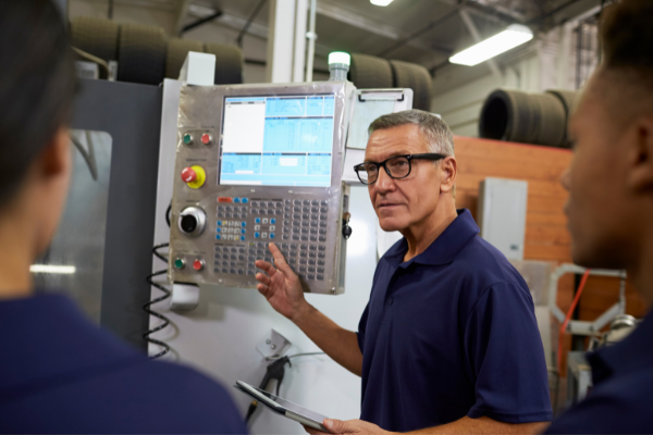
Conclusion
The machinist’s job is to provide the manufacturer with parts that are as close to perfect as possible. The closer to perfect a part is, the less product is wasted and the more profit the manufacturer will make. If a part requires an interrupted cut or an undercut, or if there are internal corner radii, the number of options one has when cutting that part gets limited. How do you know if your design can be easily manufactured? Refer to the guidelines outlined in this document, and you’ll be on your way to avoiding some of these common mistakes.